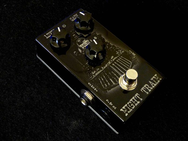
Great sounding, simple to build low to mid gain overdrive pedal.
Circuit is designed around unusual "anti-parallel" combination of NPN and PNP silicon transistors, originally developed by Arsenio Novo and presented on rec.music.makers.guitar newsgroup.
Currently my favorite overdrive pedal!
Design:
I designed an adaptation of the circuit back in 2007, the project evolved and finally got optimized down to a very basic 4 transistor circuit, which in my opinion delivers the most interesting sound.
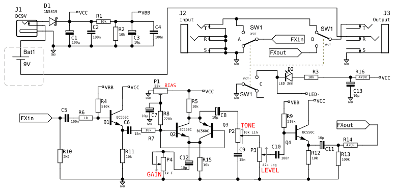
Circuit is very simple and built with four common available silicon transistors. Starting from the input, the signal goes into high input impedance buffer, which drives the main distorting transistor pair. The gain control is achieved with changing the amount of negative feedback (1kC potentiometer in series with the bypass capacitor C12). Distorted signal is fed into a simple tunable lowpass filter (Tone) and into the main output volume control. The last transistor serves as an output buffer keeping the output impedance at low and constant level. Please note, although the schematic shows the battery power option, i didn't include it in the design presented below. If you need a battery powered version you will have to design your own enclosure.
The choice of transistors is not critical. Use anything relatively low noise for the input and output buffers, but watch out the pinout. The PCB is designed for a typical CBE pinout of the BCxxx series transistors. The main NPN+PNP pair is a place where i'd encourage to do a few experiments with different types (i installed a simple sockets to be able to change the parts). Definitely worth trying are pairs 2N3906+2N3904, BC550C and BC560C will deliver more gain. I also tried the pedal with higher power but smaller beta BD139+BD140 pair, delivering much softer and less distorted sound.
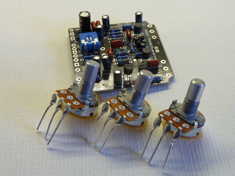
The PCB uses a classic through hole components only to make it easy to build even for beginners. After finishing the pedal the main pair needs to be properly biased. The best and simplest way to do that is to tweak the trimpot while playing and set in position where the sound will be smoothly overdriven and not gated. Pluck the strings and check if the sound does not abruptly decays.
I have incorporated two bypass options on the PCB. One is a standard 3PDT footswitch with two sections switching the signal and one for the status LED. The other options is the Millennium Bypass ( (c) by R.G. Keen). It uses a few parts extra and a DPDT footswitch.
Schematic:
Build:
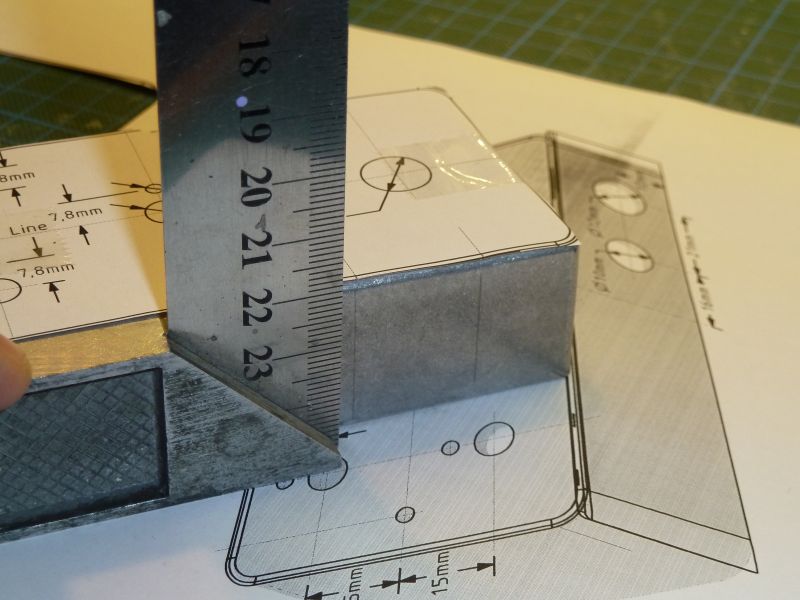
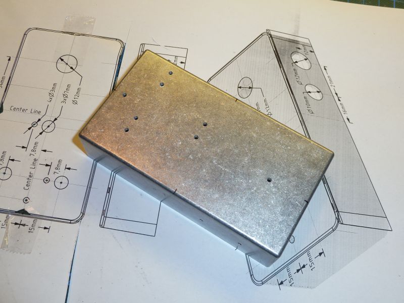
The box is a standard Hammond 1590B type. Print out the drill layout in 100% scale. Mark the center points on the enclosure edges.
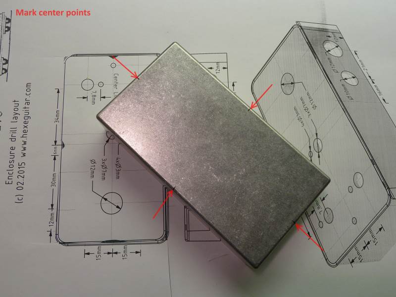
Cut out the top view of the box and align the center lines with the markings.
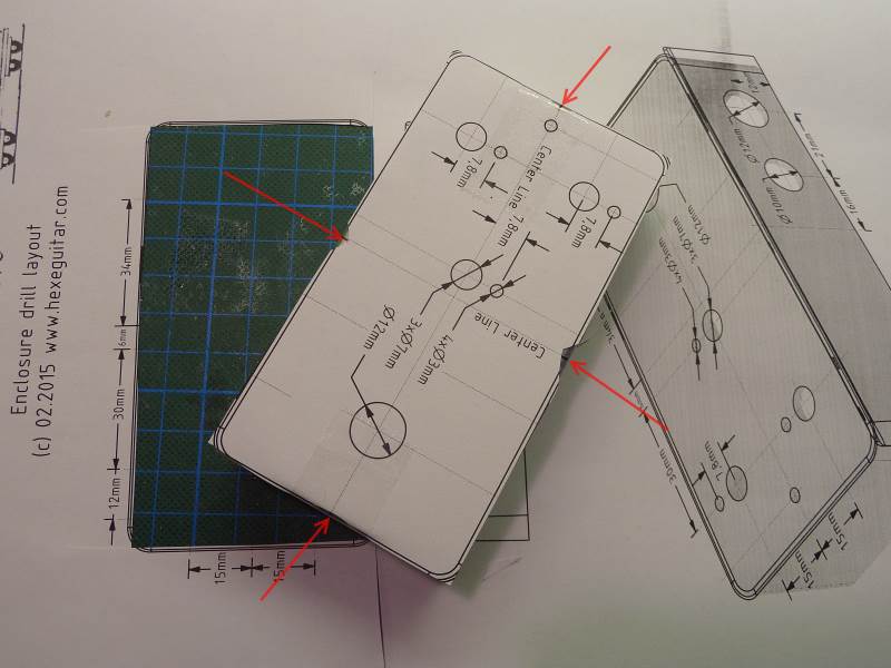
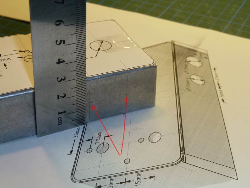
Using a 90 degree L ruler, mark the center axes for the jacks.
Mark the center points.
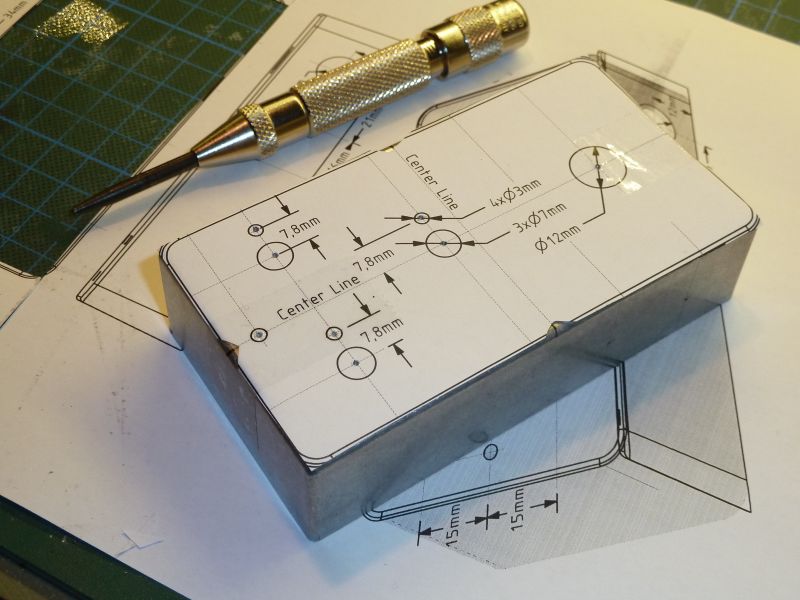
Center punch all the points.
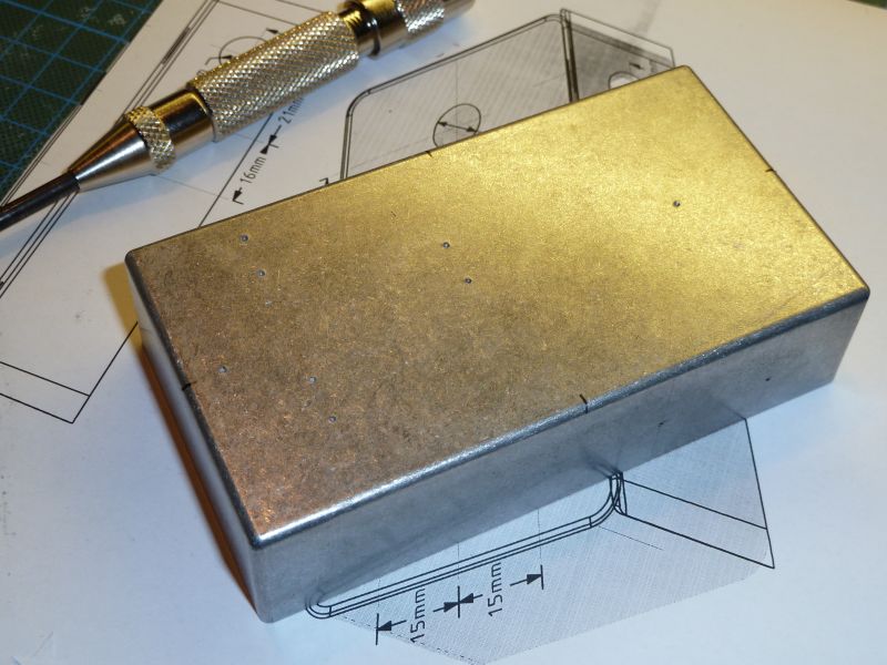
Box prepared for drilling.
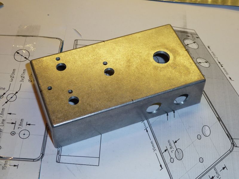
You may skip this step, but i recommend doing it to ensure the drilling will be precise: drill a 2mm pilot holes.
Completely drilled box. Now sand it and clean it with isopropyl alcohol.
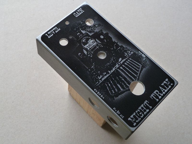
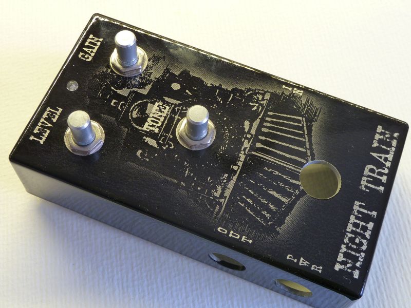
Print out the decal and apply it on the top of the enclosure.
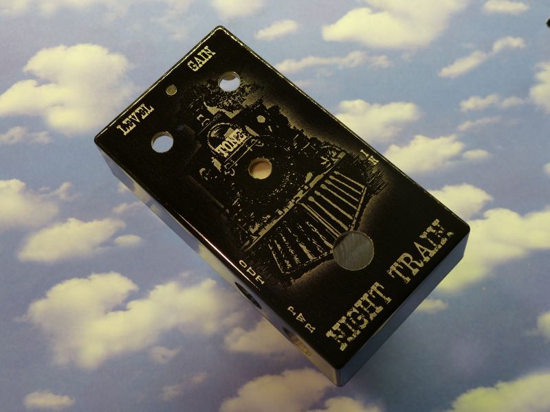
Prime, paint the sides and put a few thin layers of clear coat. The box is finished.
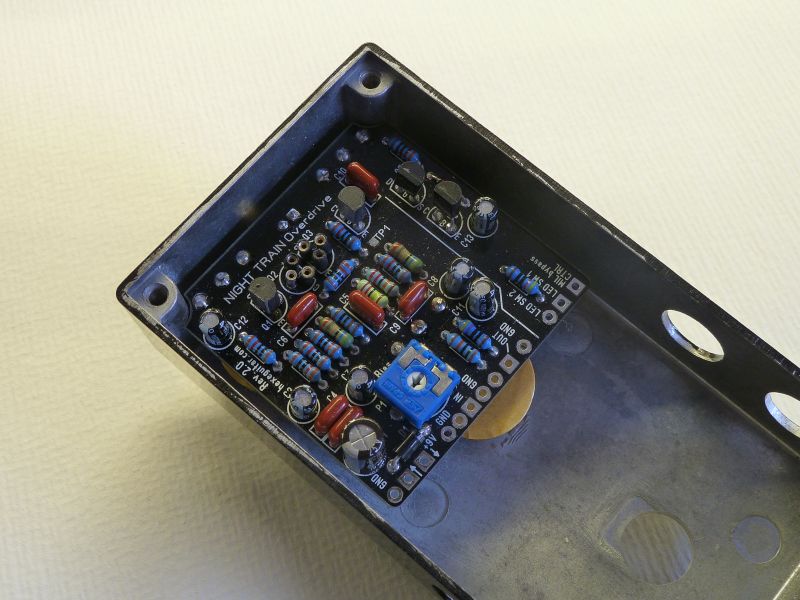
Populate the PCB and solder the components. Prepare the potentiometers (sorry, standard short legged ALPHAs were too big, you need to improvise a little bit).
Install the potentiometers and the LED, do not solder them yet!
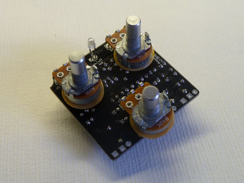
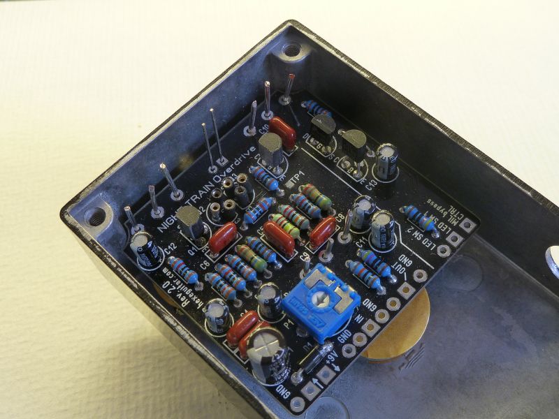
Install the PCB into the enclosure, position the LED.
Flip the pedal over. Now the pots and the led are positioned, we can start soldering them to the PCB. This method ensures there will be no mechanical stress applied to the pcb and parts.
Solder the pots and led terminal and cut them off.
Install jacks and the footswtich, finish the wiring according to the schematic. The PCB allows to use two types of bypass: standard one using a 3PDT footswitch, where one section switches on and off the LED, or Millennium bypass (by R.G. Keen, www.geofex.com), using a 2PDT footswitch. As you can see i have used the latter method.
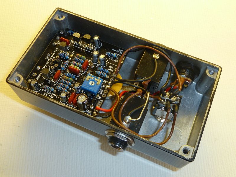
Enjoy!
Media:
Pedal was used as a main source of distortion in this video too:
Design files including:
- Schematic and bill of materials.
- Enclosure drill layout.
- Graphics (decal) project.
- PCB assembly guide.
are available in the Github repository:
https://github.com/hexeguitar/NightTrainOD
Click to open in new window
git clone https://github.com/hexeguitar/NightTrainODPCBs can be ordered directly from OshPark.