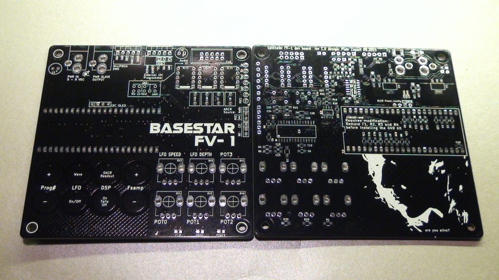
FV-1 DSP development board.
Versatile tool for developing FV-1 based projects with a few extras to expand the chip's features.
As of Oct 2019, when i wrote this article, the CY8CKIT-049, required for the project, has been discontinued and is no longer produced. Some distributors might still have them in stock. Please check the availabilty before you start building it.
Project background/operation:
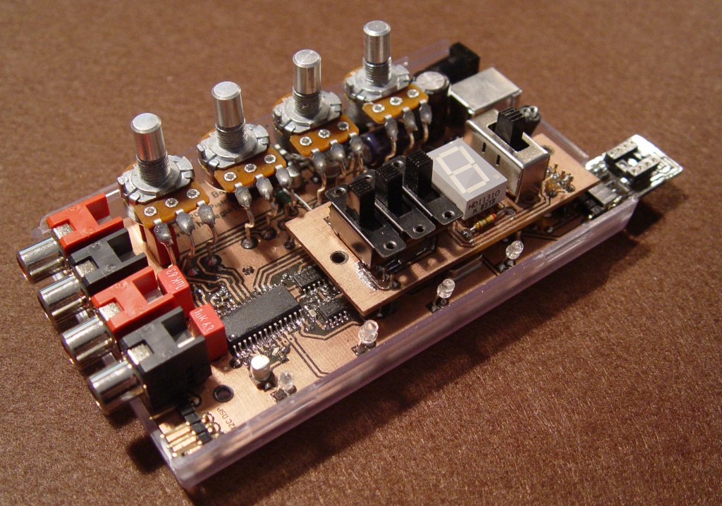
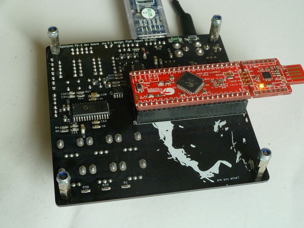
After using my old (designed around 2010 - see the picture on the right) Spin FV-1 dev board for the last few years i finally decided i need something more sophisticated. Whether it was that or maybe my increased interest in Cypress PSOC microcontrollers, it pushed me to design a new, modern and better equipped development base for the very nice DSP made by Spin Semiconductor.
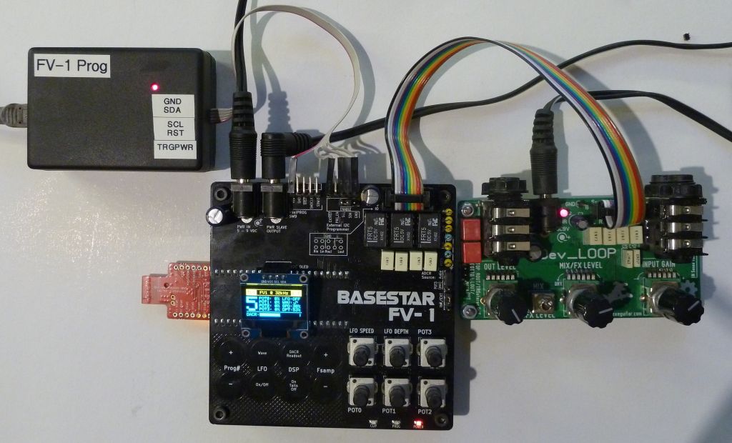
Basestar FV-1, inspired by one of my favorite series of all times is a part of a larger modular DSP development system, including Dev_LOOP, which is used as an analog IO board (impedance matching, level adjustment, mixer, stereo/mono routing).
Another goal of designing the new FV-1 dev board was to exploit a few tricks in order to get more control inputs. Besides the usual 3 CV inputs (POT0-2) the board can generate a modulated square wave signal, which fed into one of the audio ADC inputs can be translated into a quickly updated fourth way of controlling the parameters. Of course, having that option i couldn't resist and added a multi waveform LFO section which opens up a lot more possibilities.
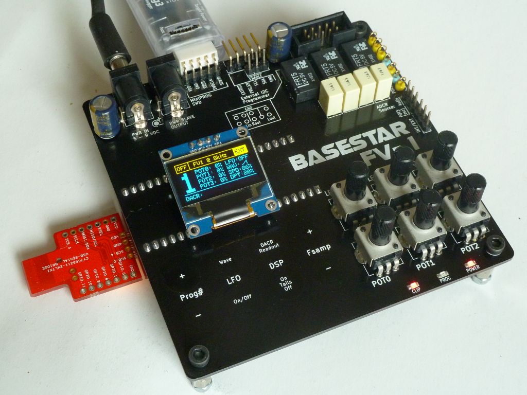
The boards uses capacitive sensing push buttons instead of mechanic ones, continuous parameters are controlled via traditional pots. The main controller doing all the housekeeping work is Cypress PSoC4200 series MCU (CY8CKIT-049). Data is displayed on a small I2C driven OLED.
Development system:
the board is designed as a part of modular DSP development system including the following components:
- Basestar FV-1 dev board.
- Dev_LOOP analog IO front end.
- FV-1 EEPROM Programmer or FV-1 devRemote
Operation modes:
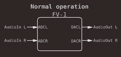
Default Stereo Mode:
Both DSP channels are used to process two audio channels.
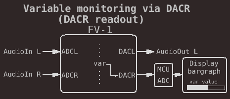
DACR readout mode:
Special mode used to monitor the value of any variable used in the DSP program. The output of the DACR will be sampled and displayed as bargraph allowing to observe that value while the DSP program is running.
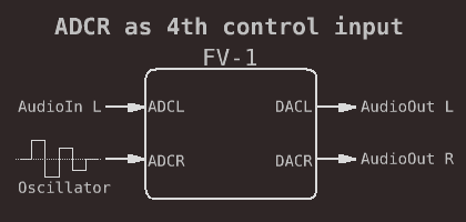
4th control input/LFO:
Right audio channel can be used as a 4th control input. Since the input is sampled at the audio sampling rate, the parameter update is much faster than using the default POT0-2 inputs, which opens up a few more options like an external LFO.
The audio inputs on the FV-1 are biased at Vdd/2 and expect an AC signal. To use it as control input the signal has to be AC, too. The board has its own square wave oscillator with it's amplitude controlled by the POT3 or LFO, if engaged, fed into the ADCR (use the ADCR Source jumper to activate that option).
Using the POT3/LFO mode:
To make a use of the ADCR control input in your program the AC signal has to be converted into DC by using a simple envelope follower. Here is an example code snippet:
equ POT3    reg0    ;POT3 = 4th control input
equ POT3flt reg1    ;POT3 filter reg
                    ;ensure ACC is empty
rdax ADCR,1.0       ;read ADCR into ACC
absa                ;|ACC|
rdfx POT3flt,0.0005 ;filter
wrlx POT3flt,-1     ;the envelope
wrax POT3,0         ;POT3 ready to use
Buttons:
- Prog# +/- : DSP program number (1-8).
- LFO Wave : one of the 7 available LFO waveforms:
- Sin
- Triangle
- Ramp Up
- Ramp Down
- Hypertriangular
- Random Step
- Square.
- LFO On/Off.
- DSP Bypass: controls the relay based DSP bypass system, 3 settings:
- OFF (DSP bypassed completely)
- Tails (only the input of the DSP is muted)
- ON (DSP on).
- DACR Readout: a special mode, which may come handy while working on a new DSP programs. When activated, it mutes the Right output audio channel and reroutes the DACR output to one of the ADC channels on the microcontroller. The value is sampled and displayed as a bargraph. This feature can be used to monitor any parameter value sent to the DACR output on the DSP.
- Fsamp +/-: DSP clock value, 7 available settings:
- 11kHz
- 16KHz
- 22kHz
- 32kHz
- 44KHz
- 48KHz
- 52KHz
Pot controls:
- POT0-2: standard FV-1 control inputs.
- POT3: controls the amplitude of the square wave generator, fed into ADCR can be used as 4th control input. Also, controls the bias of the waveform if the LFO is activated.
- LFO Speed: 0-10Hz LFO rate control.
- LFO Depth: depth control works in conjuntion with the POT3/bias control.
Power I/O:
- PWR IN: DC5.5/2.1mm center negative jack, 5-9VDC input.
- PWR Slave: direct thru jack to send the power to other modules (ie. the analog IO).
Analog I/O
IDC10 connector carrying stereo in and out signals, compatible with Dev_LOOP audio connector.
Digital I/O:
- External I2C programmer - used to connect an external I2C EEPROM programmer and reset the DSP after updating the firmware.
- MiniPROG SWD - 5pin connector for Cypress MiniPROG debugger.
- USB - part of the CY8CKIT-049 kit, provides an USB to UART bridge.
Jumpers:
- INT/EXT - internal or external DSP program bank.
- ADCR Source - selects the signal routed to the ADCR input - default audio R channel or POT3 control signal.
- EEP PROG Enable - allows/denies the access to the I2C bus.
Test points:
- L and R input audio signal.
- L and R output audio signal.
- POT3 control signal (amplitude modulated square wave).
- GND for reference.
Design files are available in the github repository:
https://github.com/hexeguitar/BasestarFV1
Click to open in new window
git clone https://github.com/hexeguitar/BasestarFV1